
Requirements elicitation and documentation using

(Tool for Requirements Elicitation and Documentation)
The first phase in software development is requirements engineering. In this phase the stakeholders’ requirements for the system to be developed are collected, evaluated, and documented. The biggest problem faced by the developers is to get the stakeholders involved in this phase and capture the requirements from the stakeholders point of view. The software industry is today moving towards this more user-oriented view, and there are in use several methods to aid in this task. We have described and compared three of them: scenarios, scripts, and use cases. In this thesis we also describe our approach to make the early phases of software development more user-oriented. This approach is built around use cases, since we have found them to be the easiest for the stakeholders to understand. Finally, we describe the tool we have constructed that embodies our approach. It aids in the administration of use case models and the generation of the object model and the documentation.
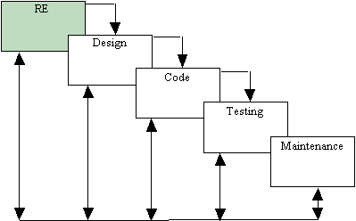
Picture 1: The classic life cycle [PRE94].
The first phase in software development is Requirements Engineering (RE), as shown in picture 1. This is where the customer’s, or the end user’s, requirements on the system to be developed are collected, evaluated, and documented. There are already in use several methods, languages, and tools to support this work, and added to them lately have been object-oriented approaches.
Object-Oriented Analysis (OOA), attempts to model a problem domain in terms of a collection of interacting objects. Each of these objects provides a well-defined set of behaviors and attributes and are drawn from the vocabulary of the problem domain. OOA deals with what a system is supposed to do rather than how to do it [BOO94][MON92][RUB92].
The object-oriented process is well-suited to describe a system proposed by a customer, since with it the developers can provide a more natural model of the system. But the methods available today don’t deal with the biggest problem in requirements engineering: the stakeholders, the real producers of requirements, are not taken into account when the collecting, the evaluating, and the documenting of the requirements is done. What we want is to get the stakeholders involved in the development process to capture the requirements from their point of view [RUM94]. This approach will make it possible for the stakeholders to verify that the requirements captured are correct. The software industry is today moving towards this more user-oriented view on RE. What is needed is a method which is easy to learn but still can be used as basis for producing a more formal requirements document, since this is necessary for the following development steps. The method should appear to the end users as informal and not too restrictive.
We have therefore developed a method that allows the stakeholders to enter their requirements in an informal way by describing use cases. Our approach aims to capture the requirements from the stakeholders’ point of view, and still be usable as basis for a more formal requirements specification.
Use cases are ways that end users can interact with the system. They describe the system’s structure as it appears from the outside, from the end user’s point of view. It is not necessary for the stakeholders to concern themselves with the internal structure of the system. The use cases are then classified and object models created. An object model shows the objects in the system and the relationships between these objects. The model also shows the attributes and operations that characterizes each class of objects. However, this model is too complex in order to communicate requirements between the developers and the stakeholders, which is why you need the use cases [JAC94a][RUM91]. With the object models that describe the system to be built, a more formal document can be produced, in the notation of choice.
In this thesis we first discuss and compare some of the different methods used to capture the functionality of a system, methods that make it easier for the stakeholders to specify and verify their requirements. After that we discuss our approach to solve the problem of getting the end users more involved in the development process and, to finish off, we describe the actual prototype that embodies this approach.
In this section we describe three ways of capturing the functionality of a system: scenarios, scripts, and use cases. We explain how and why some object-oriented methods use these constructs and outline each one of these methods briefly. The differences between scenarios, scripts and use cases are discussed, and a summary of their pros and cons is offered.
A scenario is a time-ordered sequence of events, where an event is something that occurs whenever information is exchanged between an object in the system and an outside agent, such as a user of the system [RUM91]. It describes a specific need that is fulfilled by a number of objects working together [COA95]. The scenarios specify what the system is supposed to do and for whom and with whom it is supposed to do it. In picture 2 we show an example of a scenario open_door. Every scenario corresponds to a path through a state diagram [RUB92]. A state diagram consist of states and transitions between these states. In our example (see picture 3) there are, besides one start state and three end states, two states where a choice of action has to be made. These two states are Verify card and Verify code. A transition is a connection between two states and will move the control from one state to another. In picture 3 examples of transitions are Invalid card and Valid code. A state diagram is prepared for each object class with nontrivial behavior showing the events the objects receives and sends [RUM91].

Picture 2: An example of a scenario.
Why use scenarios? They are a great help in finding additional objects and to better distribute and refine the responsibilities between objects. Scenarios are also used to gain better understanding of system dynamics to assess model completeness and to test an object model. It is not practical to consider every scenario within a system of any significant size, so the developer should focus on the so-called key scenarios. The most interesting scenarios are those that start with a human interface or a system interface and wind their way through the objects in the system [COA95]. These scenarios show the interaction with the system, which is what we need the stakeholders to verify.

Picture 3: An example of a state diagram.
The most famous method that uses scenarios is the Object Modeling Technique (OMT) [RUM91], which is widely regarded as one of the most complete object-oriented analysis and design approaches published so far, especially since it has been extended during the last years with a use case front-end instead of, as in the beginning, assuming the existence of a requirements specification.
The main phases of OMT are conceptualization, analysis, system design, and object design. In this discussion we are only concerned with the first two phases. In conceptualization the requirements are identified using use cases (described in 2.3), which will capture the requirements from the stakeholders point of view.
In the latest version of the method the analysis phase has been divided into a macroprocess and three microprocesses, one for each of the traditional OMT models: the object model, the dynamic model, and the functional model. Each of the microprocesses is a series of low-level steps to follow in building a model. These steps may be invoked many times as part of the higher level macroprocess. In the macroprocess the domain object model and an application model is built, the latter on top of the first [RUM95].
In the microprocess the object model is built first, then a dynamic model for every object is developed. The functional model, which is not used by every practitioner, is developed last [GRA94]. The object model describes the static structure of the system, i.e. the structure of the objects. The object model provides the essential framework into which the dynamic and the functional model can be placed [RUM91]. The dynamic model shows the time-dependent behavior of the system and the objects in it. Scenarios are used to describe a sequence of events that occurs during one particular execution of a system. The scope of a scenario may vary, but OMT uses them primarily to construct the dynamic model of the system, i.e. the object interaction, which comes after the object-modeling process. Scenarios are more technically defined in terms of an already existing object model and no help in identifying the initial model [COY93]. (A more thorough description of OMT can be found in [RUM91].)
Another important object-oriented analysis and design method, which makes use of scenarios is the Booch-method [BOO94]. Booch divides his development process into a macro- and a microprocess. The macroprocess is the controlling framework for the microprocess and consists of five steps. The first is conceptualization, which is where the core requirements are established. The second is analysis, where a model of the desired behavior is developed. After that comes design, where the architecture is created, and evolution, where the implementation evolves. The last step is maintenance, when post delivery evolution is managed. This broad process results in a number of measurable products, e.g. scenarios, and activities that permit the development team to make meaningful risk assessments and make corrections to the microprocess [BOO94].
The microprocess is driven by the stream of scenarios and other products that emerge from the macroprocess. It consists of four steps. The first is to identify all the classes and objects at a given level of abstraction, and then identify the semantics of these classes and objects. The third step is to identify the relationships among these classes and objects, and the last step is to specify the interface and then the implementation of these classes and objects. Booch recommends the use of scenarios to drive the process of identifying classes and objects and to aid in the consideration of how these objects work together [BOO94].
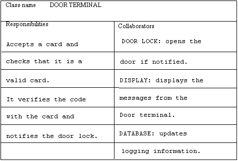
Picture 4: An example of a CRC card.
It is during the analysis phase that the scenario planning takes place. Class/Responsibilities/Collaborator (CRC) cards are used in the brainstorming about each scenario. CRC cards are index cards with lines where the developers write the information in pencil to be able to change it easily. This information includes the name of the class, its responsibilities, and its collaborators, as shown in picture 4. They have been found to be an effective way to analyze scenarios and also useful in enhancing the communication among developers [BOO94]. Other advantages are that they are easy to understand, to use, and to modify. Their disadvantage is that they quickly become unmanageable as their number increases. (A more thorough description of Booch’s method can be found in [BOO94].)
Scripts are used to capture scenarios (i.e. not scenarios as described in 2.1). Scripts describe a system from an external perspective as opposed to an internal perspective, as done by scenarios. They help conduct the problem analysis and capture it in an explicit notation for the purpose of communication [COY93]. The basic idea behind a script is directly related to the operational concept of an object-oriented system. They are designed to capture how a collection of entities in the system communicate. Each of these entities provides a set of well-defined services that may be used by other entities [RUB92].
Object Behavior Analysis (OBA) [RUB92], relies on scripts to record the use of the proposed system. The motivation for OBA is that a more effective way of finding objects is needed, compared to the methods used today. OBA is a five step process. First the context for the analysis is set. In the second step, the developers try to understand the problem by focusing on behaviors, and in step three define objects that exhibit these behaviors. The fourth step is to classify objects and identify their relationships, and the last step is to modify the system dynamics [RUB92].
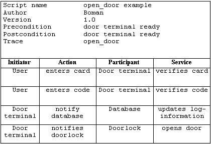
Picture 5: An example of a script.
Finding the system behaviors, which is done in the second step, is accomplished by eliciting scripts from interviews and documents. The identified behaviors are then assigned to parts of the system, the participants and their responsibilities are identified, and initiators distinguished [RUB92]. In our example (see picture 5), one of the initiators is the user and one of the participants is the door terminal.
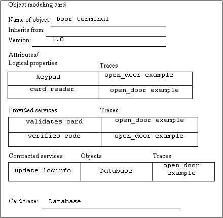
Picture 6: An example of an object modeling card.
Modified CRC cards, called object modeling cards, are used to record the details of objects and discover classification, usage structures, and other associations, which are important for object modeling [COY93][GRA94]. For the card reader object in the open_door example an object modeling card can look like picture 6. (A more thorough description of OBA can be found in [RUB92].)
Another method that uses something called scripts is the Semantic Object Modeling Approach (SOMA) [GRA95]. In SOMA the scripts are called task scripts. We have found that they resemble use cases more than scripts, and therefore will be described in section 2.3 instead of in this section.
In trying to make the software engineering process more user oriented, developers have found that use cases are an excellent medium for communicating requirements between them and the end users. Use cases are also an excellent way for capturing the functional requirements of a system, since they help to structure the object models developed later into manageable views.
Research in cognitive science characterizes stories as a basic representation for everyday knowledge, cultural heritage, descriptions, and explanation of events. Narratives have been found to be the preferred medium to describe and explain things. People narrate a scenario of use instead of citing the underlying principles. The narratives people use to understand and organize their lives are strongly bound to specific contexts and situations in the world, and this knowledge about everyday events is organized into story-like scripts [CAR94]. In cognitive science the terms scenario and script are used in the same sense as we use the term use case. In Human-Computer Interaction (HCI) and usability engineering, which will be discussed next, the terms have the same meaning as in cognitive science.
Much contemporary technical activity in HCI, can be seen as a feedback relation between tasks and artifacts. The tasks people engage in and those they wish to engage in define the requirements for systems developed in the future. From the standpoint of usability engineering, which focuses on the ”user friendliness” of a system [PRE94], a new system or application must be viewed as a transformation of current tasks and practices. The developers need to consider that they are redesigning human activities in order to make them easier to carry out, or more effective in achieving a goal. Narratives, or scenarios, are an excellent medium for representing the possibilities for users embodied in a new system. Users need not understand the underlying design or implementation in order to provide change requests given in the form of scenarios [CAR94].
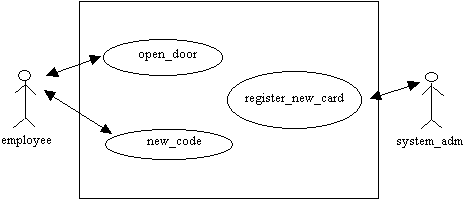
Picture 7: An example of a use case model.
A use case model consists of actors and use cases, and defines a system's behavior. An example of a use case model is shown in picture 7. In this model there are two actors, employee and system_adm, and three use cases: open_door, new_code, and register_new_card. The double-headed arrow between an actor and a use case indicates that the actor initiates that use case. The use case model defines a system’s behavior through a set of use cases.
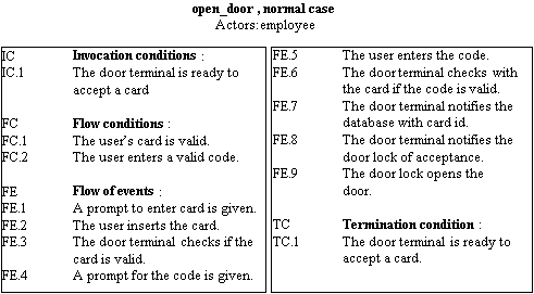
Picture 8: An example of a use case as an ordered list of steps [REG95].
Actors represent everything that exchanges information with the system. This role is not necessarily played by humans only, but by any entity that interacts directly with the system. Users interact with a system by interacting with its use cases, and the collection of all the use cases for the system represent everything the users can do with it. Every use case must be started by an actor. One way of writing use cases is as a list of ordered steps, as in picture 8, another as plain text:
open_door is started by employee when she wants to open a door. She must each time enter her code, which is then validated against her card id. Each time she opens a door her card id is logged in a database.
The object model is not replaced by the use case model, but is developed orthogonal to it. In this way the use cases help structure the object models into a number of different views, which is practical to manage complexity. One view is drawn for each use case and the objects that participate in that use case are modeled. The total responsibility of an object is reached by integrating all its responsibilities found in all the use cases in which the object has a role [JAC94a].
An object-oriented approach supporting use cases is Objectory [JAC92]. It is unusual among object-oriented methods in trying to address the entire software development life cycle. In Objectory it consists of the stages analysis, construction and testing. Five different models are developed: the requirements model, the analysis model, the design model, the implementation model, and the test model [GRA94][JAC92].
The requirements model aims to capture all the functional requirements and is created from the requirements specification. This specification is developed outside the scope of Objectory. To capture the functionality of the system use cases are employed and a use case model is constructed as a part of the requirements model. The use case model is used to generate a domain object model with objects drawn from the entities of the business. This model is then converted into an analysis model by classifying the domain objects into three types: interface, entity, and control objects. This split is done to make changing the behavior easier as requirements evolve. The analysis model is constructed with the requirements model as basis to give the system a robust and changeable structure. The requirements model and the analysis model form the output from the analysis phase of the Objectory life cycle. The analysis model is then converted to a design model expressed in terms of blocks that are implementations of one or more objects. The implementation model aims to implement the system and the test model is used to verify the system.
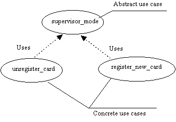
Picture 9: Examples of abstract and concrete use cases, and the uses association.
In the use case model actors and use cases are described. An actor represents a certain role that a user can play. That is, users are the actual persons who use the system. One user can play the role of several actors, e.g. in our example (see picture 7) the same person may act as employee and system_adm. When an actor initiates a use case it is in Objectory viewed as an instantiation of that use case's class, like an object Volvo may be an instance of a class CAR. A use case class is a description of how users interact with a system, and the collection of all such descriptions specifies the complete functionality of a system [GRA94][JAC92].

Picture 10: An example of the extends association.
Use cases can be combined to avoid redundancy and enhance reuse. Some use cases might be part of other use cases or used by other use cases. In Jacobson’s use case model, there exist two different associations to combine use cases, uses and extends. If it is possible to extract similar sequences from different use cases, these are called abstract use cases. The original use cases that share the descriptions are concrete use cases. The extracted abstract use cases are called abstract because they are meaningful only for describing parts shared among other use cases. Abstract use cases cannot be instantiated, i.e. they only exist in combination with concrete use cases using them, hence the name uses for the association between the concrete and the abstract use case. In picture 9 the concrete use cases unregister_card and register_new_card both use the abstract use case supervisor_mode, since both unregister_card and register_new_card included a sequence where the system administrator authenticated herself. This sequence was then broken out and an abstract use case was created.
The other type of association is called extends and is useful to introduce new use cases into a system as extensions of already existing use cases. We first describe the basic use cases and then describe how to enhance them to allow more advanced use cases. The new use cases may depend on the basic ones and are said to extend the old ones. The use case where the new functionality will be added should be a complete, meaningful course of events in itself [JAC94b]. In picture 10 the use case new_code extends the use case register_new_card, which means that the first adds new functionality to the latter, but they can both stand on their own. (A more thorough description of Objectory can be found in [JAC92].)
Rumbaugh proposes to model uses associations and extends associations using only one single general relationship [RUM94], even though they are different ways to come up with new use cases. A use case can be seen as a sequence of events, which can be grouped into subparts of the entire use case. These subparts are called subsequences by Rumbaugh and can be singled out, e.g. in the case of uses and extends. Both uses and extends are simply ways of adding an additional subsequence into a base sequence. In the uses association, the subsequence is mandatory, i.e. an essential part of the entire use case. It is partitioned out because it may be reusable as part of other base sequences. In the extends association, the subsequence may stand alone. In this way both uses and extends can be treated as special cases of a directed adds association between a base class and an additional case [RUM94]. According to Jacobson this supports a functional decomposition of the system, which could easily lead to a functional structure rather than an object-oriented one [JAC94b].
Usage Oriented Requirements Engineering (UORE) [REG95], is an extension to the Use Case Driven Analysis (UCDA) proposed by Jacobson et. al. [JAC92]. Regnell et. al. find that the use case model we get from UCDA is just a loose collection of use cases, which are later used directly to create the analysis model. This model describes the structure of the system and is a step towards design. What we really would like is one complete model which captures the functional requirements and system usage without any design aspects at all. UORE therefore adds a synthesis phase (see picture 11), where use cases are formalized and integrated into a Synthesized Usage Model (SUM). This model captures the functional requirements and system usage in a more formal way than the use case model [REG95].

Picture 11: The UORE process [REG95] p. 41.
UORE consists of two phases. The first is analysis, which resembles the original UCDA. It consists of identifying use cases and actors and unifying the terminology. The second phase is the synthesis phase, where the synthesized usage model is created by formalizing and integrating use cases, which can then be verified. The differences in the analysis phase from UCDA are the changed semantics of actors and use cases, the strict application of the single-actor view, and the structured description of use cases, as shown in picture 8. In UORE, an actor does not necessarily model a single role played by a user, as in UCDA, but represents a user that belongs to a set of users with common behavior and goals. The single-role semantics of UCDA may lead to use cases that show too narrow aspects of the system usage, since the behavior a single actor may exhibit is rather limited. This makes it more difficult to analyze the interaction between different system operations. Use cases are regarded as examples of system usage, as experimental material, since they are expected to be further investigated and modified during the synthesis phase. This differs from the original approach where use cases are regarded as classes. In UORE each use case describes the system behavior from only one actor’s point of view, and communication between actors is done through the system. This single-actor view makes the use case concept simpler [REG95]. (A more thorough description of UORE can be found in [REG95].)
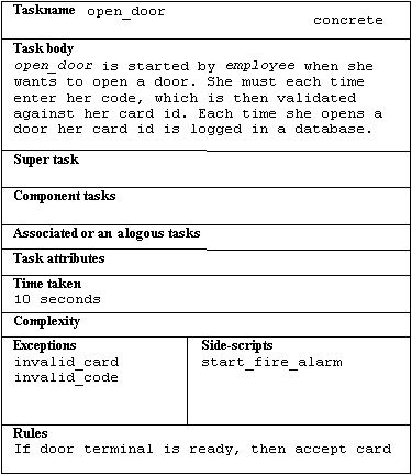
Picture 12: An example of a task card.
The Semantic Object Modeling Approach (SOMA) [GRA95], is a method that uses something called task scripts, which we have found is very similar to what we call use cases. Therefore a short description of SOMA will be given here. Task scripts are used to represent stereotypes of the tasks the system must help the users perform. They are not the same as tasks done for the user or scenarios representing actual examples of a task, since we want to model humans using tools and not automata replacing people. The set of all task scripts form the task object model in SOMA. The tasks are recorded on task cards (picture 12). Since the task scripts consist of sentences, a linguistic analysis of them will reveal objects. These objects are used to construct the business object model. The task object model is an object model in its full sense but the objects in it represents users' tasks and not domain and application objects as in the business object model. The textual analysis of the task scripts will reveal these business objects. A manual transformation process then converts the business object model into an implementation object model, which can be expressed in the semantics of some particular design notation, like Booch's, or programming language, like C++ [GRA95]. (A more thorough description of SOMA can be found in [GRA95].)
Scenarios, scripts, and use cases may at first glance appear to be just the same thing with different names. It’s true that they do have many common traits, but there also exist differences, which will be pointed out in this section. Their advantages and disadvantages when looking at their support for making the software development process more user oriented will also be discussed.
Scenarios, scripts, and use cases are all used as a help to develop systems from the stakeholders point of view. In the methods that uses these three constructs, they are all used to support the capturing of the functionality of a system in an easy-to-understand way. The stakeholders are able to verify from the scenarios, scripts, or use cases that the system shows the intended behavior. To further enhance the ability for developers and stakeholders to communicate and understand each other, the terminology is unified by a dictionary created from the vocabulary taken from the scenarios, scripts, and use cases.
All three constructs aid in finding objects in the system and defining their behavior and interaction with each other. The difference is where they are introduced into the development process. Scenarios are mainly used to construct the dynamic model of the system and therefore introduced after the object model is built. There is a slight difference between Booch’s approach and OMT. Booch uses scenarios to identify the objects and classes of the system as well as their dynamic behavior, while OMT does not use them at all to build the object model. Scripts are no help in creating the initial requirements model either, but are introduced when it is time to build the object model, i.e. the existence of an initial requirements document is presumed. They are used to find the objects of the system. These objects are found identifying the behaviors of the system, as specified in requirements documents and interviews done with the stakeholders. The script shows how the objects found interact with each other, and displays this interaction in a way that may be communicated to the stakeholders. Use cases are introduced as early as in the requirements elicitation phase, where they are an aid in building the requirements model. The stakeholders enter their requirements in the form of use cases, which let them think of the system in a way very natural to humans. These use cases become the backbone of the development process and control the formation of all other models.
Naturally, scenarios, scripts, and use cases all have their advantages and disadvantages. Scenarios, being introduced after the object model is built, are no help in finding the initial requirements model. They concentrate on finding how the objects in the object model interact. Scenarios describe the system from an internal perspective, which means that the system must be understood in terms of objects and classes, making it more difficult for the stakeholders to grasp. Moreover, the use of state diagrams to model object interactions makes it hard for the stakeholders to verify that the system behavior is correct. Scripts on the other hand are used when building the object model. The system is divided into objects and classes, and the interactions between them are identified, but on a higher level than with scenarios. The system is viewed as a black box and the stakeholders need not concern themselves with the internal structure of the system. Use cases describe the system as a black box as well. Since they are introduced as early as in the requirements elicitation phase, the complete functionality of the system may be verified before the development process is continued. The requirements are traceable right through the life cycle due to the fact that use cases control the construction of all other models. This makes the structure of the system more flexible. On the other hand it is hard to predict use cases for all possible system interactions right from the start.
Throughout the literature on the subject of scenarios, scripts, and use cases there is a big mix-up of terminology, making it difficult to distinguish what separates the three terms. In some cases scenarios are treated as examples of use cases, in other they are more technical and concerned with the internal structure of the system. The same is true for scripts. In this thesis we have chosen one interpretation of the terms. According to our view, use cases are the most user-oriented approach, being the easiest and the most natural for the stakeholders to understand. The level of abstraction is the highest, leaving the internal structure of the system the concern of the developers and not the stakeholders. They also make it possible for the stakeholders and developers to verify the behavior of the system before going any further, and they aid in creating all other models. In table 1, we have summarized the differences between scenarios, scripts, and use cases.
| Scenarios | Scripts | Use cases | |
| Used in which phase of the development process | Creation of the dynamic model from the object model | Creation of the object model from the requirements | Elicitation of the requirements, and creation of the object model |
| View of system structure | Internal | External | External |
| Degree of formality | Formal | Semiformal | Informal |
Table 1: A comparision of scenarios, scripts, and use cases.
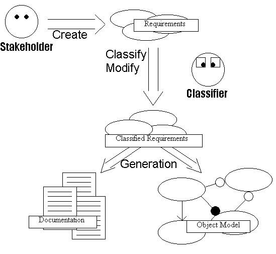
Picture 13: The requirements collection and documentation of our approach.
In this section we describe our approach to requirements engineering. We have adopted the concept of use cases, since we have found that they are an excellent way for stakeholders to enter their requirements in a manner already familiar to them. Our use cases mostly resembles the use cases described by Regnell et. al. in [REG95], but also have some traits from the use cases used in Objectory ™5B_JAC92]. The differences from Regnell’s use cases are that we have added a short summary for each use case, along with the name of a contact person and the names of the related use cases. This information is suggested by Vemulapalli [VEM95] to be useful. Additional information added to each use case are the names of the use cases that extends it and the abstract use cases that the current use case uses. We have adopted Jacobson’s view on extends and uses [JAC94b], which means that abstract use cases can be extracted from existing use cases, or an existing use case can be extended with another use case.
Our approach is designed with two different types of users in mind. One is the stakeholder, the end user of the system, the other is a more advanced user, one we call the classifier. The end user creates the requirements and the classifier modifies and classifies the created use case model (see picture 13).
The first type of users are the end users of the proposed system, i.e. the real producers of requirements. They will only need to be familiar with the concept of use cases to be able to use the system to enter their requirements. The end user enters the flow of control in the use case as a detailed description in natural language. This is the first version of the requirements.
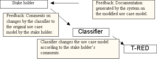
Picture 14: The feedback cycle of the use case collection after the initial use case model is entered.
The other type of user, the classifier, needs more knowledge to be able to perform his task. He will add classification codes to each use case. The classifiers job is to take the important words in the detailed description of a use case and classify them as words, actors or use cases. The classifier should also break out important repetitions of use cases and create abstract use cases and use them in the modified use case model. The procedure of the lexical analysis of the words could be automated, but the method works fine with a human classifying the words as nouns and verbs. The classifier might very well be the same person as the end user entering the use case. The ideal situation would be that a couple of end users will enter use cases, and one end user will get some education and act as classifier. The advantage of having a classifier with knowledge of the system to be built is great, since the classifier could do changes that the end users are likely to agree with. Each stakeholder would be responsible for the use cases that she is most familiar with.
The documentation of the use case system can be produced at any time during the classifying process. This allows the contact person, i.e. the end user who entered the use case, to check what changes the classifier have made, and provide feedback to the classifier (see picture 14).
In this chapter we first describe the collection and classification of use cases, and then move on to explain how the classification is used in the creation of object models.
We have chosen use cases for collecting the requirements, since we have found that they best fit the description of being informal but yet not too restrictive. We believe that the end user can easily understand how use cases work since they are similar to many everyday descriptions, like cooking recipes or technical manuals for household appliances. The method allows the users to enter their requirement descriptions as use cases, from which the system can automatically generate an object model.
Actors represents everything that exchanges information with the system. The actors are not necessarily roles played by humans, but may be played by any entity that interacts directly with the system. One person can play several roles and thereby represent several actors, e.g. both be an administrator and an employee. Each actor uses the system in different ways and when an actor uses the system, he initiates a use case [JAC94a].
The information required for an actor is the name of the actor and a short description of the actor’s role in the system. Since every use case have to be initiated by an actor, the user must first enter at least one actor description into the system before any use cases can be entered.
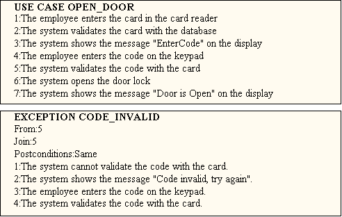
Picture 15: The exceptions have references to the use case descriptions.
The information about a use case is more extensive than the information about an actor. The information required includes the name of the use case, the name of the actor that initiates the use case, a short summary of what the use case does, preconditions, postconditions and a complete description of the basic flow of control with separate descriptions for alternative courses, called exceptions. The important bits in the use case are the detailed description and the exceptions. The detailed description is the part that describes the flow of control in the use case. The description of one use case is entered in natural language, but as an ordered list (see picture 15). The reasons for this approch are to keep the descriptions simple and that every sentence or event must have a number that the exceptions can relate to.
The exception is an alternative course of events from the normal flow of control. It must be explicitly stated when they will be invoked. They have a detailed description of their flow of control, which follows the same restrictions as the use case description. The exceptions resembles the use cases, with the exception that they inherit all the information that is not explicitly stated from the invoking use case. They have a point in the flow of control from the use case, where the exception is invoked, and there is also a possible join point. The exceptions can raise other exceptions, in the same way use cases can. This makes it possible for exceptions to express repetition, e.g. limitations on the number of tries a user can have when entering an erroneous code. The postconditions in an exception is used if an exception changes the postconditions of the invoking use case or exception.
The use cases that the end user have entered will usually need some structuring. It would help if another end user could read the use cases through and ask the writer of the use case to clarify parts that are diffuse. If this is done by a person with some linguistic skills, the language will be checked at the same time. If the structure of the descriptions are bad, the automatic generation of an object model will be hard, if not impossible.
Since some parts of different use cases might model the same events, these parts can be broken out to create a special type of use case. This type of use case is an abstract use case. The use cases from which the abstract use case was broken out is called concrete use cases. An abstract use case is not a use case in the real sense. It cannot be instantiated at any time, but must be invoked by another use case. The abstract use cases have no initiating actor, no contact person, no preconditions or postconditions, but they may have exceptions just as the concrete use cases. Several use cases might all use the same abstract use case, this is the reason for creating an abstract use case. For instance, if both the checking in of a first class passenger and a charter group in an airline system needs to check in luggage in the same way, an abstract use case check in luggage might be in place. This abstract use case will then be used by the two concrete use cases.
The important words in each use case description will make up a dictionary, which unifies the terminology. The explanations of the words in the dictionary are later used to explain the object model.
The creation of the object model is done by analyzing the text. The informal English description is transferred into a formal specification by a simplified version of the approach described in [SAE89]. In this approach the objects and methods are found by organizing the important words into word classes. That is, nouns become the objects and verbs the methods. The technique is an old one and is often criticized as not scaling up. The problem is that the object models quickly becomes to large to handle [ABB83]. The use case descriptions on the other hand are not as complex as specifications in pure natural language, which makes the process feasible when using use case specifications.
The lexical analysis finds the subject, predicate and different types of objects. The system creates a class from the indirect object, which becomes the name of the class. The system then creates methods from the predicate and direct objects (the terms direct and indirect object are grammatical terms). Finally, the direct objects become attributes and if they are classes in their turn a has relationship is registered. The subject is used to create the uses relationships from the object class created by the subject.
The classes in the object model contain some basic information of the class. First there is a short description of the class, this information is extracted from the dictionary and the word descriptions. There are also methods and attributes in the classes. The relationships that exist are has and uses. There are also traces to the use case model. The use case from which a method derived is entered on the method entry line in the class file.
In this section we describe the example system that is used throughout this thesis. The system is a simple access control system and the idea to the system was found in [AND95].
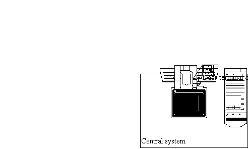
Picture 16: Schematic sketch of the hardware in the ACS.
The example system has got door terminals and electronic locks in every door. Access to different rooms can be granted to different users of the system. The users use common smartcards for identification along with a personal code for authentification.
The person with physical access to the central unit is the administrator of the system. At this computer she can register cards to the system, both common users, security guards and new administrators cards. The administrator can even do some administrating from the door terminals.
The central hardware of the system is the central unit, which is a computer with software administrating the system. It is used for storing the log files and the database of users and their cards. A printer is also available for printing various logs. The computer is connected to a phone, which is used to alert the fire department in the event of a fire alarm. At every door there is an electronic door lock and a door terminal. The door terminal has got a card reader, a display, a timer and a keypad. The card reader is a reader that can read smartcards. For output from the terminal the display is used. It can display four lines of text with a line length of 20 characters on the screen at the same time. Input to the door terminal is though the keyboard, which is a numeric keypad and has got 10 digits, a ‘#’ and a ‘*’ key. See picture 16 for a sketch of the system.
The cards used by the users are common smartcards. These cards stores the code of the card in the card. This allows the card to handle the authentification of the users. The identification of the cards is done by the door terminal.
The administrator can register a new card at the central unit or at a door terminal. After identifying and authenticfiating herself, the administrator may register a new card to the system. The new card is classified and information about the user is added. The information added is the social security number or another identification number.
Once a card is registered to the system, access control can be added. The administrator can register which doors the card should have access to. This can be done both from a door terminal and from the central unit.
The administrator is also allowed to unregister a card and withdraw access privileges. This is done in the same manner as the registering and granting of access, i.e. both from a door terminal and from the central unit.
When the user has been granted access to a room, she can open the door by inserting her card in the card reader. The door terminal asks her for her Personal Identification Number (PIN). The PIN is validated with the card, and if it is correct, the door is opened. If the user enters an erroneous code three times, the access privileges are withdrawn.
When a door has been opened, a timer is started. If the door is not closed within 2 minutes, an alarm is triggered. The security guard is alerted and a log message is sent to the main system. The security guard must use his card in the alarming card reader for the alarm to be reset. If the security guard does not reset the alarm in another 2 minutes, the alarm is once again triggered.
A new card is programmed with a PIN, which can later be changed. It can be done by a person in possession of a card of which she knows the PIN. The system asks the user to enter the new PIN twice, which is done to prevent the user from entering a code with typing mistakes.
From every door the fire alarm can be started. Every door terminal has a sign with a text saying “In case of fire, press 112”. When the system is idle and this code is entered on the keypad, a fire alarm is triggered. The system is said to be idle whenever it is not busy with handling any use case.
The administrator can check who entered which rooms. This is done by generating an access log. The log can be shown on screen, written to file, or printed on the printer. The log lists which cards have been used to open which doors.
The administrator can also check where fire alarm has been started, if and where someone has entered an erroneous code, or if a door was open too long. This log can be written to screen, file, or printer, just like the access log.
The prototype was created to show that the approach proposed by us is feasible. The prototype can be used by the stakeholders to enter actors and use cases to model a system. Detailed information about actors and use cases are added in natural language with some restrictions. When a use case model has been entered using the prototype, the system is able to generate hypertext documentation of the use case model. When a classification of the detailed description in every use case is done, the system can generate an object model. This classification process is not as straightforward as the entering of the use cases and requires some linguistic skills. During this process the user classifies the words in the detailed description by their word classes. We currently support the word classes noun, verb, actor and use cases.
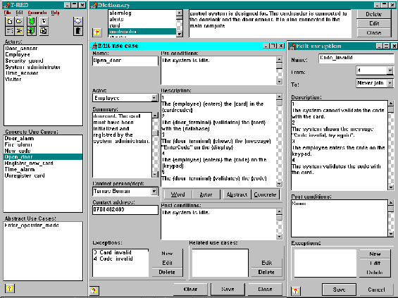
Picture 17: A complete view of the prototype.
When a project is manipulated, no explicit project saving is needed. The system works continuously on the files. Actors, use cases, and the dictionary are stored separately when they are created and changed. In every form there is an option to save the changes. When this is done, the change is saved to disk and the project is updated. An open project is always editable, i.e. the prototype is not a tool for examining a finished system, but a tool for editing it. For simply displaying the use case model, the documentation generation is used to produce the documentation in the form of hypertext. Links between use cases, actors and words are created, but also links to the object model if it has been generated. The syntax of the hypertext conforms with the Hypertext Meta Language (HTML). The generated documentation can be viewed with any browser that can view HTML documents version 1 and above.
The object model is created in the form of class files. Every file contains methods, attributes, has and uses relationships of one class. These files are pure textfiles and are portable to other platforms.
The prototype was implemented using Borland Delphi for Windows (16 bit version). The operating system was the Swedish version of Microsoft Windows 95 and the computer an IBM clone with an AMD-486 DX66 processor and 12 MB of RAM. Snapshots of the system were made in this environment. The prototype is customized for a minimum resolution of 1024x768. For an example of how the prototype might look when all forms are open see picture 17.
When starting the prototype, the user is presented with a simple form. This form shows all created actors and use cases in listboxes. The menu’s available are File, Edit, Generation and Help. The File menu have got the usual New, Load, Close and Exit choices. There is no Save or Save as items, this is because the saving is done continously by the save buttons in the different forms. There is a choice Remove Project, which removes the current open project permanently from disk. All subdirectories and control files are removed. Other choices in the File menu is the New Actor and New Use Case choices, these two choices opens the new actor and new use case form respectively.
The Edit menu have two entries, Edit actor and Edit use case. These two open a new form for the actor or use case who is marked in the listboxes in the main form. The form presents all information about the actor or use case, and allows changes to be done.
The last menu is the Help menu. The only entry in this menu is the About dialog. The help text on different forms can only be shown by pressing the question mark buttons in the different forms.
All functions presented by the menu’s in the form are also available as quick buttons. The quick buttons are the small buttons at the top of the main form. By placing the cursor over the quick button and holding it still for a while, a small hint text for the button is shown. For a snapshot of the main form, see picture 18.

Picture 18: The main form.
The basis for the system is the use case concept. The concept is simple and can be learned in short time. The prototype allows the stakeholders to enter the use cases in a natural way. Since every use case must have an initiating actor, actors must be entered first into the project. Actors and use cases are tightly coupled to each other.
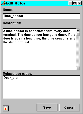
Picture 19: The edit actor form.
When creating an actor, a simple form is presented. The form when creating a new actor lacks the list of related use cases. This entry is displayed only when editing an existing actor. The form is displayed when pressing the actor quick buttons on the top of the main form or choosing from the actor alternatives from the menus. A snapshot of the form Edit actor can be seen in picture 19. The form contains three entries: the name, the description, and related use cases.
The name must be unique to the project. Two projects can have an actor with the same name, but two actors with the same name must not exist in the same system. The file structure and the contents of the files will be described in detail later.
The description is a textfield. The description is later used to add comments to the object models. If the actor becomes a class in the model, the actor description will be added to the class file as its description.
In the form there is a list of related use cases, but this list is not editable. It is automatically updated from the use case creation and editing process. When an actor is mentioned in a use case, the name of the use case is added to the actor as a related use case.
The creation of a use case is more complex. The form is the same both when editing an existing use case and when creating a new one. The form to be filled in contain more information than the actor form, as can be seen in picture 20.
Every use case must have a unique name. It must be unique within the project, but different projects may have use cases with the same name. The name of the use case will decide what filenames the files containing the data related to the use case will have.
The summary of a use case is added to aid the stakeholders in getting a quick overview of the system. The summary is not used for any documentation or object model generation.
Every contact person and the corresponding phone number (or address) are stored in a special directory. The name of the contact person must be unique to the project. Different projects may have different contact persons with the same name. If a contact person already exists, the associated phone number is displayed. If the number is changed, the number in the corresponding text file is also changed. This ensures that the contact person’s phone number is always up to date. The phone number is used to contact the person who entered the use case. If the use case is modified by the classifier, the changes have to be validated by the stakeholder who entered the use case. The phone number entry in the use case form need not necessarily be a phone number, it can be any string. The straightforward way is to use it to enter the phone numbers of the contact persons, but Facsimile (FAX) numbers, Short Message System (SMS) numbers or e-mail addresses could be used instead. The automatic notifying of changes could easily be handled by scripts sending messages to the contact persons.
The post- and preconditions are text fields in which one can enter specific conditions that have to be fulfilled before the use case is invoked and when it has finished. They are not used in the generation of the object model, but may be used for validation purposes.
The detailed description of a use case is the key to the use cases. Here the stakeholder can enter the flow of events in a use case. The advantage of the use case approach is that this detailed description can be entered in natural language, which makes it easy for a person to learn the process of use case modeling. In this prototype the syntax is important. The sentences should be on the form: ”Someone performs action on something”. Here ”someone” might be an actor or some other entity. For instance ”5 The card reader shows the message ‘Card is invalid’ on the display” is a valid entry. All activities are numbered successively. More information concerning the syntax and the detailed description is given later when the generation of the object model is described (section 5.3).
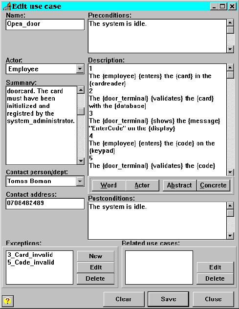
Picture 20: A snapshot of the edit use case form.
Exceptions can be entered by pressing the Add button beside the Exceptions list box. When pressing the Add button, a blank exception form is shown. When this exception is entered it will show up in the list box. To edit an exception, simply double click on an exception or mark one and thereafter click on the edit button. To remove an exception, mark the exception and press the Remove button. (See section 5.1.2.2 below for a more detailed description.)
The related use cases listbox is filled during the classification phase. When a word in the description is classified as a use case, the use case name will show up in the related use case list box. To edit a related use case, mark the use case in the listbox and press the Edit button (or double click). When the Close button is pressed after a related use case is edited, the old use case will be loaded to the form. If a use cases is to be removed, mark it and press the Remove button. The use case will then be removed from the related use case list.
There are three buttons at the bottom of the form. They are Clear, Save and Close. The Clear button clears the form and discards all changes in the form. The Save button saves the use case permanently to disk. The Close button closes the form without saving.
Abstract use cases are created to be able to reuse parts that are shared by several use cases. The difference between an abstract use case and a concrete one is that an abstract is not initiated by an actor, and cannot be performed as a separate use case. For instance, both the use case register_new_card and unregister_card relies on the system_adm to prove his identity. This process could be extracted and expressed in a new abstract use case. This use case cannot be performed alone, but relies on a concrete use case. The use cases register_new_card and unregister_card are said to use the abstract use case supervisor_mode (see picture 9).
There are three entries in the abstract edit and create form: the name, the description and the related use cases. The name must be unique to the current project. The description is in the same form as the detailed description of the concrete use case. The classification of the description is not implemented in this prototype, but would be similar to the classification of a concrete use case.
The list of related use cases in the abstract use case form contains all use cases that are using this abstract use case. The lists in the abstract use cases are not editable, but are automatically updated when concrete use cases are classified.
See picture 21 for a snapshot of the form for editing and creating the abstract use case.
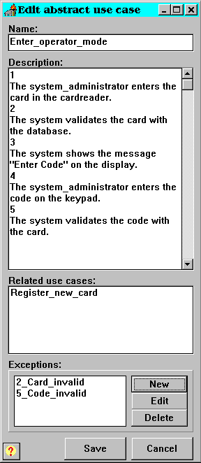
Picture 21: A snapshot showing the editing of an abstract use case.
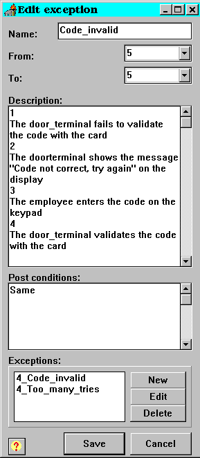
Picture 22: A snapshot of an edit exception form.
Exceptions should be added whenever something diverges from the normal flow of control. The entries in an exception are the name, the entry and exit point, a description, additional comments and postconditions. The name needs only be unique for every use case and not for the whole project. That is, two exceptions can have the same name as long as they are not associated with the same use case.
After an exception is raised, the use case can resume the flow of control. The exception form has got two fields controlling this. The first is called From:, this is the field where the stakeholder can express when in the use case the exception might be raised. The To: entry is the point where the use case resumes control. The To: entry can have the value Never joins which means that the use case does not resume control when the exception is done.
The description in the exception is used in the same way as the detailed description in the concrete use case. This includes the adding of exceptions, one exception might be raised recursively. For an example see picture 22. The exception Code_invalid is an exception that relates to the event when an incorrect code has been given. When the user of an access control system tries to open a door, but fails to enter the correct code, this raises an exception in the use case open_door (see picture 20). The exception asks for a new code and validates the same, if the validation once again fail, the same exception is raised. The exception might have a limit on the number of tries the user have. If this is the case, one exception controlling this must be added.
Raising an exception may effect the postconditions of a use case. Differing postconditions can be entered in the Postconditions: field/entry. The reserved word same refers to the postcondition of the invoking use case or exception.
Currently the object model generation is not using this description, but in general the description of an exception can be treated in the same manner as the detailed description of a concrete use case is treated in this prototype.
When a use case is entered, the classification process can begin. In the current prototype the important words in the detailed description are classified. The important words are decided by the user of the system. The abstract use case descriptions and the descriptions of the exceptions should also be classified in the same manner.
The classifying process consists of marking the word to be classified and thereafter choosing a classification of it. If the word is an actor, abstract use case or concrete use case, the corresponding button is pressed. In picture 20, they are the buttons beneath the Description field. The actor or use case must exist to be a valid classification and the system checks if this is the case. An error message is produced otherwise.
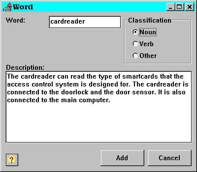
Picture 23: A snapshot of the new word/edit word form.
If the word button is pressed, a new form is displayed containing the name of the word. See picture 23 for an example of this form. If the word exists in the dictionary, the description of the word is shown in the Description field. If the word is a new one, a description should be added and a classification as noun, verb or other must be given. The prototype does not support a structured dictionary, i.e. synonyms and superordinates cannot be specified. This would be expected from a real implementation. When the Add button is pressed, the word is added to the dictionary.
When a marked word in the detailed description is classified, every entry of the word in the use case is automatically marked in the detailed description. In the current prototype, brackets are added around the classified word.
For instance, ”The card reader shows the message ‘Card is invalid’ on the display” would after a complete classification look like: ”The {card reader} {shows} the {message} ‘Card is invalid’ on the {display}”.
The dictionary entries will later be used to add comments to the object models. The description in the dictionary of the words are stored in the class files for the corresponding classes. The dictionary is also used when generating the documentation. When generating the documentation, the words are linked so that their description can easily be shown.
When the project is completely entered, an object model can be generated. The prototype generates new models from scratch. The algorithms used are simple and no automatic textual analysis of the use cases are made. This can be done due to the presumption that the detailed description of each use case is entered in a natural language with some restrictions. This syntax was described earlier when the entering of the use cases was described (see section 5.1.2).
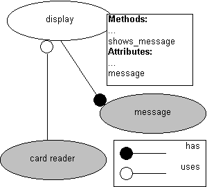
Picture 24: An example of a generated object diagram.
Consider the sentence ”The {card reader} {shows} the {message} ‘Card is invalid’ on the {display}”. When the object model is generated this entry will add the method shows_message and the attribute message to the display class. If message is a class, a has relationship will be added to the display class. Furthermore a uses relationship will be added to the card reader class since it uses the display class. See picture 24 for an object model of the added information, where the gray parts in the picture are assumed to have been created by other use cases.
Since the creation process is automated, some work needs to be done to the object model after the generation. Repetitions of methods and attributes are common due to spelling mistakes or different formulations from different users entering use case descriptions. The names of methods often require some modification. How the information is stored in the files is discussed in the File structure section below (section 5.5).
During the project development, or after it is finished, documentation can be generated. The generated documents follow the HTML standard and can be viewed with an appropriate HTML browser. See picture 25 for an example of an ordinary browser showing the main page of the project documentation.
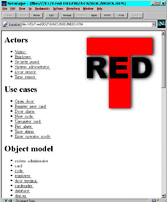
Picture 25: A snapshot of a Netscape browser showing the generated use case documentation.
The documentation of the use case model consists of the Actors, Use cases and the words in the dictionary with hypertext links in-between. The documentation is a direct translation of the use case model from within the system. All entered information is used and the documentation can be distributed by a world wide web (WWW) server. The end users can easily get hold of the current use case model and check that the flow of control of the use cases confirms to their demands.
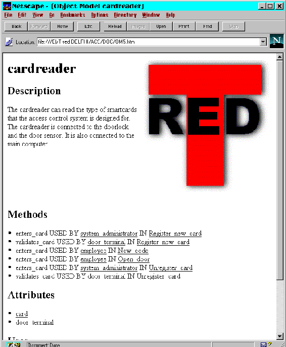
Picture 26: Snapshot of a browser showing the class documentation of the object class card reader.
When generating the documentation, the object model will be generated first. The object model will then be linked to the related use cases. This allows the analysts to check the requirements specification if questions arise during the analysis phase. See picture 26 for an example.
In this section the file structure of a project entered using the prototype will be described. We also describe the system files used by the prototype itself.
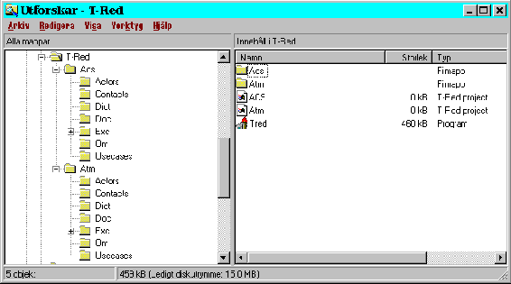
Picture 27: A snapshot from the Explorer in Microsoft Win95
The data of the whole system is stored in text files. Every project has a separate directory which contains the data of the project. Subdirectories are Actors, Contact, Dict, Doc, Om, Usecases, and Exc. The Exc directory in its turn contains subdirectories for every use case. The files are identified by their suffixes and location. The file structure as presented by the Explorer in Microsoft Windows 95, where two projects ATM and ACS have been entered, is displayed in picture 27.
The Actors directory contains information about the actors. The files with suffixes .act are the actor files. They contain the name of the actor, the description of the actor and the related use cases to the actor.
The Contact directory contains information about the different contact persons. The suffix of the contact files is .con and the information in the files is the name of the contact person and the contact string. The file is a simple text file with the name on the first row, and the rest of the file represents the contact string.
The Dict directory contains the entries in the dictionary. The files contain data about words and the suffix is .wrd. Every word has got a separate text file. The contents of a word file are the name, type and description of the word.
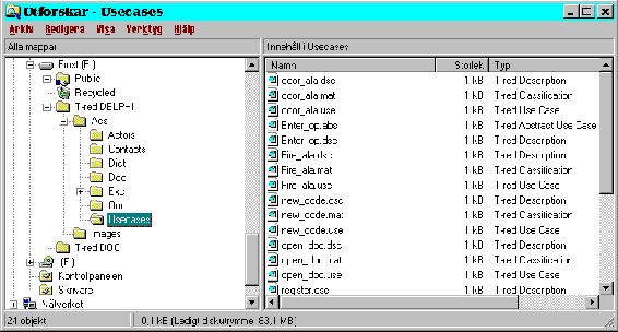
Picture 28: File browser showing the contents in a use case directory.
The use cases directory contains four types of files. The contents of the files are concrete use case data, abstract use case data, detailed descriptions and classification words. The suffixes are .use, .abs, .dsc and .mat respectively. The concrete use case data files contains name, initiating actor, related use cases, summary, contact person, preconditions and postconditions related to one use case. The name of the file is decided by the name of the concrete use case. The abstract use cases have got onlyl the name and the related use cases stored in a file associated to one use case. The description files contain the detailed description of both concrete and abstract use cases. This adds the limitation that a concrete and an abstract use case may not have the same name within one project. Finally, the classification files contain the words that are classified in the detailed description. When a word is classified in a use case, the name of the classified word is stored in a file associated with this use case, the file has got the suffix .mat. Since the suffix is the same for both concrete and abstract use cases, an abstract use case cannot have the same name as a concrete use case. See picture 28 for a snapshot of the file browser showing the contents in the use case directory for the ACS example.
In the Exception directory every use case get one subdirectory each. This is done so that different use cases can have exceptions with the same name and still contain different descriptions. The exception subdirectories contain two types of files, the exception files and the exception description files. They have the suffixes .exc and .dsc. The exception file contains the name, the exit point, the reentry point, number of iterations and the postconditions. The filename of the exception is a combination of the name of the exception and the entrypoint, this allows different exceptions with the same name within one use case. This can be done as long as the entry point is not the same.
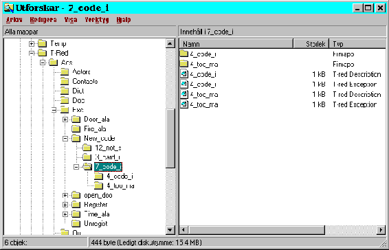
Picture 29: The filebrowser showing the exceptions files.
The exceptions can have exceptions in their turn. These recursive exceptions are saved in subdirectories to the directory containing the exception that invoked them. For example, the exception invalid_code in the new_code use case have an exception too_many_tries. The subexceptions files will be created in subdirectories in the invalid code directory (see picture 29).
The generated documents are stored in the Doc directory. The suffix of the files are .htm and the file index.htm contains links to the complete system. There are one file corresponding to every actor, use case and word in the system.
Name: display
Every card reader has got a display to display messages on.
:Methods
shows_message used by system
:Attrib
code
message
card
:Uses
:Has
code
message
card
Picture 30: Example of the contents of a class file.
In the om directory the object model is stored. The model consists of class files with the suffix .om. The files contain name, description, methods, attributes, has relationships and uses relationships. The classes in the created model have got the following information about the object class: Methods, Attributes and Has and Uses relationships. The name and a description (the description entered in the dictionary) is also saved inhe class file. An example of what generated class file might look like can be found in picture 30.
The executable file is called tred.exe. The names of project and files are related to the working directory. When new projects are created, not only will the directory structure described before be created, but a control file, named after the project is created too. The directory structure will be created from the working directory and the project file will be created in the working directory. The suffix of the project file is .prj. The project file is used by the program to locate the different project. The project file is selected in a standard file open dialog, and the project will be set up from the directory where the project file is situated.
Every form has got a question mark button. When this button is pressed a help text is displayed. The help text is stored in the directory Help where the prototype is installed, there exists one textfile for each type of form.
This version of the prototype has got a very simple textual analysis of the use case descriptions, entered in natural language. A future system may very well be developed where the demands on the syntax in the natural language is not as strict as in this prototype.
The matching of the use cases against existing object models is a big project in itself and is not covered in this project. Therefore the reuse of old object models is not implemented but can be expected in future versions.
A tool for manipulating the generated object model should be developed. In this version the object model is saved in textfiles.
When generating the documentation, a list of the contact persons should be generated. From every contact person in this list, there should be a hyper link to all the use cases they are responsible for. This would assist the contact persons in checking whether the use cases they are responsible for seems to be correct after a change.
When the use cases are classified in the prototype, the words are marked by brackets added around the words. It would be better if they could be in a different color, inversed or hyper linked to the dictionary entries. In this prototype, when use cases are removed, the brackets around the use case name in the description have to be removed manually. This should automatically be done when removing of the use cases from the listbox of related use cases.
All text fields in the forms may be at most 255 characters, since this is the longest string allowed by the prototype development environment.
In this version of the prototype all names of actors, use cases and words in the dictionary must be unique on the first 8 characters. This is due to the Ms-DOS limitation in file name length. The names of all files except for the generated documentation files corresponds to the names of the contents of the files. That is, data about an actor named supervisor will be stored in the file supervis.act. Spaces cannot be used in the names of actors and use cases due to Ms-DOS limitations.
Classification is only possible on the detailed description, i.e. actions, of the concrete use cases. Abstract use cases and exceptions cannot be classified, they should be handled in the same way as the concrete use cases. This would allow the information collected in the abstract use cases and the exceptions to be used in the object model generation.
In this thesis we have discussed and compared some of the different methods used to capture the functionality of a system. We have also presented our approach to make the development process more user oriented, and the tool we have created to aid in the entering and administrating of use case models.
We have studied how scenarios, scripts, and use cases are used in different approaches to user-oriented RE, along with their advantages and disadvantages. Scenarios were found to be the most technical of the three, and thereby the hardest to understand for the stakeholders. Scripts are more user oriented by being introduced earlier in the development process, letting the stakeholder view the system as a black box with no concern for the internal system. They are still not used to collect the requirements from the end users, but presume the existence of a requirements document. Use cases are introduced in the requirements elicitation phase and therefore offer the highest level of abstraction for the end users.
We have found by this study that use cases best serve our purpose of being easy to learn and yet usable as basis for a more formal document. With use cases the stakeholders can enter their requirements in a way that is easy to understand and natural to the human way of thinking. Use cases may be written in natural language with or without structure. In our approach we have chosen to write use cases in structured natural language, since we have found that it enhances readability and makes the connection with the exceptions more natural. Moreover, the use cases help structure the object model developed later, and aid in finding the responsibilities of each class.
The tool we have built serves as an aid in administrating the use case models and generating the object model in a project. Use cases are entered using fill-in forms, and are thereafter classified. This is done by adding information about the important words in the use case description. The information about the words is stored in a dictionary. This information is later used when generating the object model. The object model is then generated for all the use cases in the project. All use cases and the object model are documented in HTML with hyper text links inbetween. The advantage of this approach is that it is easy to trace from which use case an object derives.
Some improvements to our approach would be the introduction of a structured dictionary, and the possibility of reuse and modification of the object model. In a structured dictionary synonyms and superordinates may be represented. This would make the object model smaller and redundancy could be removed. Synonyms would remove objects exhibiting the same behavior and superordinates would facilitate the creation of a class hierarchy.
We believe that our method, and the tool that supports it, offers an excellent way for the stakeholders to get involved in the development process. It allows the end users to enter their requirements using a method that is easy to understand, and in the end emerges in a semiformal specification for the system to be developed, without the need of a middle man.
Finally, we would like to thank our tutor Jürgen Börstler for his valuable help in the research for this master thesis, and his valuable comments on its contents.
| Actors | Actors are roles played by any entity that interacts directly with the system. |
| Conceptualization | The first phase in RE where the requirements are identified. |
| CRC card | Class/Responsibilities/Collaborator card, index card with lines used when analyzing scenarios. |
| Elicitation | To bring forth, evoke. |
| OBA | Object Behavior Analysis. |
| Object model | An object model shows the static structure of a system. |
| Objectory | Object-oriented method that incorporates use cases. |
| OMT | Object Modeling Technique. |
| RE | Requirements engineering, the first phase in software development. |
| Scenarios | Specify what the system is supposed to do and for whom and with whom they are supposed to do it. |
| Scripts | Help conduct the problem analysis. |
| SOMA | Semantic Object Modeling Approach. |
| Stakeholder | All persons, groups, or entities which have an interest in the development of the system. Among them are the end users. |
| State diagram | Diagram showing the dynamic behavior of a system, used to describe a scenario. |
| UCDA | Use Case Driven Analysis. |
| UORE | User-Oriented Requirements Engineering. |
| Use cases | Descriptions of how actors interact with system |
| [ABB83] | R. Abbott. Program design by informal English descriptions, Communications of the ACM, November, 1983. |
| [AND95] | M. Andersson, J. Bergstrand Formalizing Use Cases with Message Sequence Charts, Master thesis Lund Institute of Technology, May, 1995 |
| [BOO94] | G. Booch. Object-oriented analysis and design with applications, the Benjamin/Cummings Publishing Company Inc, 2nd edition, 1994. |
| [CAR94] | J. Carroll, R. Mack, S. Robertson, M.B. Rosson. Binding objects to scenarios of use, International journal of human-computer studies, 1994. |
| [COA95] | P. Coad, D. North, M. Mayfield. Object modelingÄWorking out dynamics with scenarios, Software development, October, 1995. |
| [COY93] | R.F. Coyne, U. Flemming, P. Piela, R. Woodbury. Behavior modeling in design system development, Proceedings of the CAAD Futures `93 conference, CMU, July, 1993. |
| [GRA94] | I. Graham. Object-oriented methods, Addison-Wesley Publishing Company, 2nd edition, 1994 |
| [GRA95] | I. Graham. Migrating to object technology, Addison-Wesley Publishing Company, 1995. |
| [JAC92] | I. Jacobson, M. Christerson, P. Jonsson, G. ™vergaard. Object-oriented software engineering-A use case driven approach, Addison-Wesley, 1992. |
| [JAC94a] | I. Jacobson. Basic use-case modeling, Report on object analysis and design, July-August, 1994. |
| [JAC94b] | I. Jacobson. Basic use-case modeling (continued), Report on object analysis and design, September-October, 1994. |
| [MON92] | D. Monarchi, G. Puhr. A research topology for object-oriented analysis and design, Communications of the ACM, September, 1992. |
| [PRE94] | R. Pressman. Software engineeringÄA practitioner's approach, McGraw-Hill Book Company Europe, 3rd edition (European adaptation), 1994. |
| [REG95] | B. Regnell, K. Kimbler, A. Wessl‚n. Improving the use case driven approach to requirements engineering, International symposium on RE, 2nd, 1995. |
| [RUB92] | K. Rubin, A. Goldberg. Object behavior analysis, Communications of the ACM, September, 1992. |
| [RUM91] | J. Rumbaugh, M. Blaha, W. Premerlani, F. Eddy, W. Lorensen. Object-oriented modeling and design, Prentice Hall, 1991. |
| [RUM94] | J. Rumbaugh. Getting startedÄUsing use cases to capture requirements, Journal of object-oriented programming, September 1994. |
| [RUM95] | J. Rumbaugh. OMT: The development process, Journal of object-oriented programming, May, 1995. |
| [SAE89] | M. Saeki, H. Horai, H. Enomoto. Software development process from natural language specification, Communications of the ACM, May, 1989. |
| [VEM95] | C. Vemulapalli. A use case FAQ (Frequently Asked Questions), Submission for OOPSLA `95 workshop on "RE: Use cases and more", 1995. |