 |

|
A model for perspective projection
This information is based upon "Practical Techniques for Producing 3D Graphical Images" by Tom Foley and Greg Nielson.
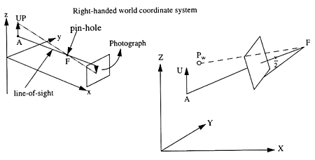
The model will be a pin-hole camera with zoom capability, which takes a square photograph. The parameters that define the position and attitude of the camera are:
F : FROM point = A point in 3D world coordinates representing the position of the camera. This will be the centre for the perspective projection.
A : AT point = A point in 3D world coordinates at which the camera is aimed, thus the vector A-F is the line of sight. The "film" or projection plane is perpendicular to this vector.
U : UP vector = A vector in 3D-world cordinates which defines the direction up in world coodinates. The camera is positioned so that the image of the UP vector on the film will be pointing up on the photograph.
v : View angle = An angle which specifies the field of view. This value directly affects the distance of the plane of projection (film) from F.
Need a viewport in NDC coordinates. The viewport determines where the pin-hole camera's "photograph" is to be displayed on the screen. To avoid distortion of the image, the viewport should be square.
Restrictions on F, A and U:
- F and A may not be the same point. This would obviously cause a problem since 2 identical points would not define a unique line-of-sight.
- U cannot be a null vector, since a null vector would not specify a unique up-direction.
- U cannot be parallel to the line-of-sight (A-F), since this would not specify a unique rotational position for the camera, with respect to the line-of-sight.
- v must be greater than zero and less than 180 degrees.
Zooming effects:
You can enlarge an image by reducing the angle of view (moving the film farther from the pin-hole). Increasing the view angle makes the image smaller. Viewing angles between 40 degrees and 60 degrees give the most realistic view.
An object in world coordinate space is typically specified as a set of 3D (X,Y,Z) vertices, and a set of edges connecting those vertices. In order to produce a 2D screen image of the object, the 3D coordinates of each vertex must first be transformed to 2D integer screen coordinates. This is called theviewing transformation.
The viewing transformation is usually done in 2 steps:
- The 3D world coordinates of each vertex (Xw,Yw,Zw) are transformed into another set of 3D coordinates (Xe,Ye,Ze) which is based upon an eye coordinate system.
- The 3D eye coordinates of each vertex (Xe,Ye,Ze) are transformed to a 2D space called normalized device coordinate system (XNDC,YNDC).
Eye coordinates are defined in a left handed coordinate system.
We want to transform the world coordinates to eye coordinates in such a way that F ends up at the origin in the eye coordinate system, A ends up on the positive Z-axis, and the UP vector ends up in the positive Y-Z plane.
World coordinate transformation to eye coordinates can be done in 5 steps:
- Translate all vertex world coordinates by an amount that moves F to the origin. For example, if F is at (3,5,7) we would subtract 3 from the X component of each vertex, 5 from the Y component, and 7 from the Z component.
- Rotate all of the vertices around the world coordinate X axis until A lies in the X-Z plane.
- Rotate all of the vertices around the world Y axis until A lies on the Z axis.
- Rotate all of the vertices around the Z axis, until the UP vector is parallel to the Y-Z plane, and has a positive Y component.
- Change the sign of the Z coordinate of each vertex. (Eye coordinates are in a left handed coordinate system).
Each of the 3 rotations can be accomplished by multiplying the (X,Y,Z) coordinates of each vertex by a 3x3 matrix, followed by the final negation to convert right-handed to left-handed coordinates.
The eye coordinate of a world coordinate vertex is:
Pe is the 3D eye coordinate point we want. Pw is the 3D world coordinate vertex. F is the from point. V is the 3x3 matrix.
Need to calculate the 9 terms of the matrix V (which is orthogonal). In eye coordinates, the Z-axis is the line-of-sight. So we get:
| c = | A - F |
| || A - F || |
The world coordinate transformation of the eye coordinate X axis is the cross product of the line-of-sight and the UP vector.
| a = | (A - F)X U |
| ||(A - F)X U|| |
The calculation of the vector, which transforms to the Y axis, is the cross product between a and c.
| b = | ((A - F)X U) X (A - F) |
| || ((A - F)X U) X (A - F)|| |
Converting in eve coordinates into 2D coordinates:
- Calculate the viewport's height
and width:
Vheight, Vwidth - Calculate the viewport's center
coordinates:
Xvcenter, Yvcenter - Map the eye coordinates of the
vertex's projection on the film to the viewport
Xn = Xvcenter + (Xe/Ze * Vwidth)/(2 * tan(v/2))
Yn = Yvcenter + (Ye/Ze * Vheight)/(2 * tan(v/2))
|
http://www.cs.umu.se/kurser/TDBC07/HT04/projects/doc/projmodel.html Responsible for the page: Pedher Johansson Last modified 2004-11-11 Copyright © 2004. All rights reserved. |